Reply With Quote
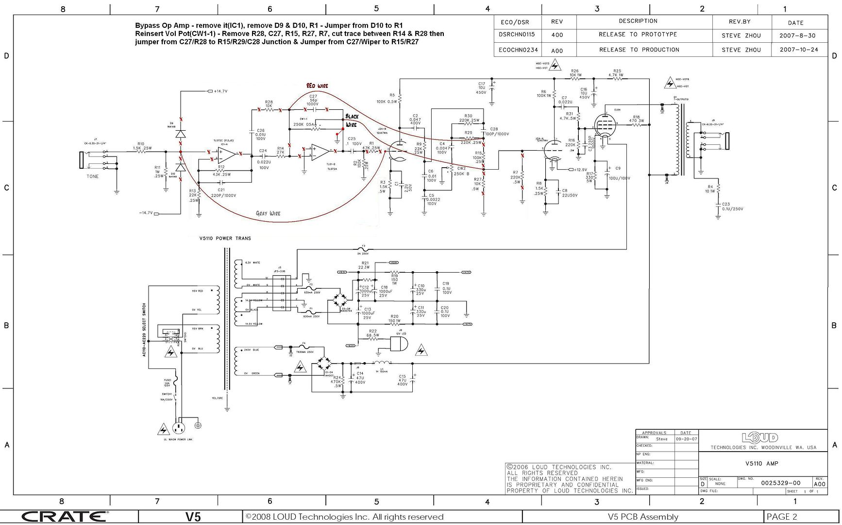
Previously on Modding the V5. In the previous post I covered the reverb tank driver circuit, now for the recovery amplifier. Here is where you get to use that TL072 op amp if you still have it in one piece. Looking at the attached schematic of the reverb recovery circuit I have made a change from most recovery circuits by adding C2 as a high pass filter. Because on the V5 that I have added reverb to, before adding reverb I had no 60 Hz hum at all (That 1 Hennery choke in the plate supply does wonders) now I have some with high levels of reverb (space the final frontier levels). As noted on the schematic a value of 100nF maybe better at blocking the 60 Hz hum. Moving on to the feed back loop of the op amp C1, R2, R3 and C3 the value of C1 keeps the op amp at unity gain at DC with a 3db down point at 140Hz this maybe another capacitor you could lower to reduce hum by changing to 220nf. If you know op amps you can see that you have plenty of gain (R3/R2 +1) approx 43 times the signal from the reverb tank. Across the feed back resistor R3 is C3 this will roll off the maximum output frequency of the amplifier at approx 4 kHz which will help prevent the possibility of oscillation of the op amp (also limit of reverb tank bandwidth). The output of the amplifier is coupled to the output level control through C4 by my calculation you maybe able to use a value of 220nf instead if you wish. Also if you added a resistor in series with the pot you could set a limit on maximum reverb level if you want. The wiper of the reverb level pot is going to be connected to R7 (220k ohms) on the Crate V5 PCB. The grounded side of R7 needs to be removed from the PCB and connected to the pot so R7 will be connected to the grid of the tube on one side and the reverb pot on the other. In the previous post I stated you need to add a 220k resistor from the wiper of the volume pot to the grid of the tube, this will sum the clean signal and the reverb signal at the grid of the tube. You will also need to add a 100 to 330pf cap from the grid of the tube to ground to help reduce or prevent reverb feedback. This mod keeps the clean signal path pure tube so you are stuck with the possibility of reverb feedback at high reverb level settings. If an op amp was used to buffer the output of the volume pot it would prevent this (you could use a cathode follower tube ckt also but). Or if an op amp was used as a summing amplifier for the clean and reverb signal this would also prevent the possibility of feedback. But the feedback will let you know the reverb is working so just consider it a test signal or you can use it to get peoples attention. One detail that is not on the schematics is decoupling of the power supplies on the bread boards I have 22-50 ohms in series with the +/- supplies with 22uf tant to ground. I took the supplies from C12+ and C13- to get approx 18 volts. If you have removed IC1 the op amp in the PCB you could reduce R19 and R20 to get +/- 18 volts at C10+ and C11- (you will need to have this circuit wired in and working to determine the value needed). I wanted greater then +/- 15 volts for maximum headroom for the op amps by there spec you could go as high as +/- 19 volts. Also I did not decouple the driver amplifier and recovery amplifier separately if you want to go for it. I would put decoupling on your proto board though because it will be located a distance from the power supply.
Next stuff to cover is hard wiring the RCA cables or installing female RCA Oh! Not politically correct sorry my bad, I meant RCA receptacles on the chassis. How to mount the reverb tank in the cabinet. How you mount the proto board is up to you.
Anyway see attachments.
Also in previous post you can see 9 volt battery clips on the proto board, I used two half dead 9 volt batterys to test the op amps before installing the board. I have a scope and signal generator to work with if you only have a meter I have to think of what you could do to test the board first.Maybe we can use the guitar as a signal generator and look for AC volts at the output of the op amp on both circuits. After an initial DC test of the circuit.
Any mistakes here please let me know,thanks.
 See you guys in a couple weeks.
 Timothy

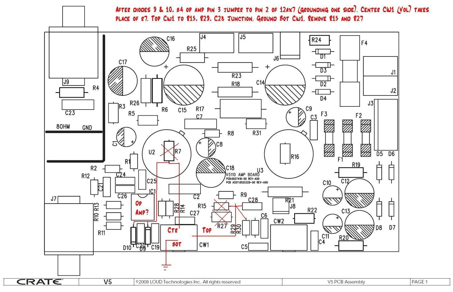
 : The second half of the preamp tube's input is pin 2 on the schematic and not pin 7. Pin 7 is the input to the first half of the triode (from the guitar jack and as shown in the schematic). I will have to pull my board and look at it again to see what I did. Sometimes I think that lower numbers come first (hence the confusion about pin 2 and 7) Remember that tubes pins are clockwise from the bottom after the space and not from the top- I made this transcription error late at night and pretty groggy. My apologies to all that have tried this and it didn't work for them.